How To Check Resistor In Pcb

Power off the circuit containing the resistor you wish to measure. Or when placed in short mode of multimeter there will be an alarm if it is shorted.

3pdt Wiring Board Pcb

3pdt Wiring Board Pcb

Pcb Design Tips For Easy Assembly Testing And Modification

Pcb Design Tips For Easy Assembly Testing And Modification

Printed Circuit Board Components Pcb Components And Pcb

Printed Circuit Board Components Pcb Components And Pcb

Step 1 remove power from the circuit containing the resistor.


Printed Circuit Board Components Pcb Components And Pcb

How to check resistor in pcb. In order to test a resistor in a pcb board. Printed circuit board pcb is the common name that is used for these electrical boards. Measure the resistance value.

In history pcbs were been developed by going through a complicated procedure of point to point wiring and these circuits were highly exposed to get failure or damage. To test a capacitor in a pcb one end of the capacitor should be removed from the circuit. This can be done by unplugging it from the mains or by removing the batteries if it is a portable device.

Generally the resistor value will be relatively accurate when it is took down from the pcb board or at least one terminal of the resistor is not soldered on the pcb board. Never measure a resistor in a circuit with a live current running through it. On printed circuit boards pcbs which serve as platforms for building the mass produced circuits commonly found in computers and other electronic systems you may have trouble recognizing the individual circuit componentsthats because manufacturers use fancy techniques to populate pcbs with components aiming to eke out efficiencies and save space known as real estate on the boards.

Turn the multimeter dial to the resistance setting. Discharge any capacitors in the circuit by touching the leads of a spare high wattage resistor to the leads. The power supply of dc voltage should match the range of the capacitor so as not to overload the device.

If it shows zero it is shorted. Keep in mind that some devices still can be charged with a potentially harmful voltage until minutes after removing its power1step 2 isolate the resistor from the circuit. An attempt to measure a resistor that is still connected to the circuit can yield an incorrect calculation as part of the circuit might also be.

In your pcb identify the resistor to be checked and place your multimeter in resistance measurement mode.

How To Test A Resistor In A Pcb Board Quora

How To Test A Resistor In A Pcb Board Quora

Optimize High Current Sensing Accuracy By Improving Pad

Optimize High Current Sensing Accuracy By Improving Pad

How To Test All Electronic Components With Multimeter Resistor Capacitor Diode Led Transistor Fuse

How To Test All Electronic Components With Multimeter Resistor Capacitor Diode Led Transistor Fuse

Resistor Resistor Used In Mobile Phone Board How To Check Resistor Types Of Resistor

Resistor Resistor Used In Mobile Phone Board How To Check Resistor Types Of Resistor

How To Find Smd Resistor Values And Size Electrical

How To Find Smd Resistor Values And Size Electrical

Help To Identify Resistor To Remove Electrical Engineering
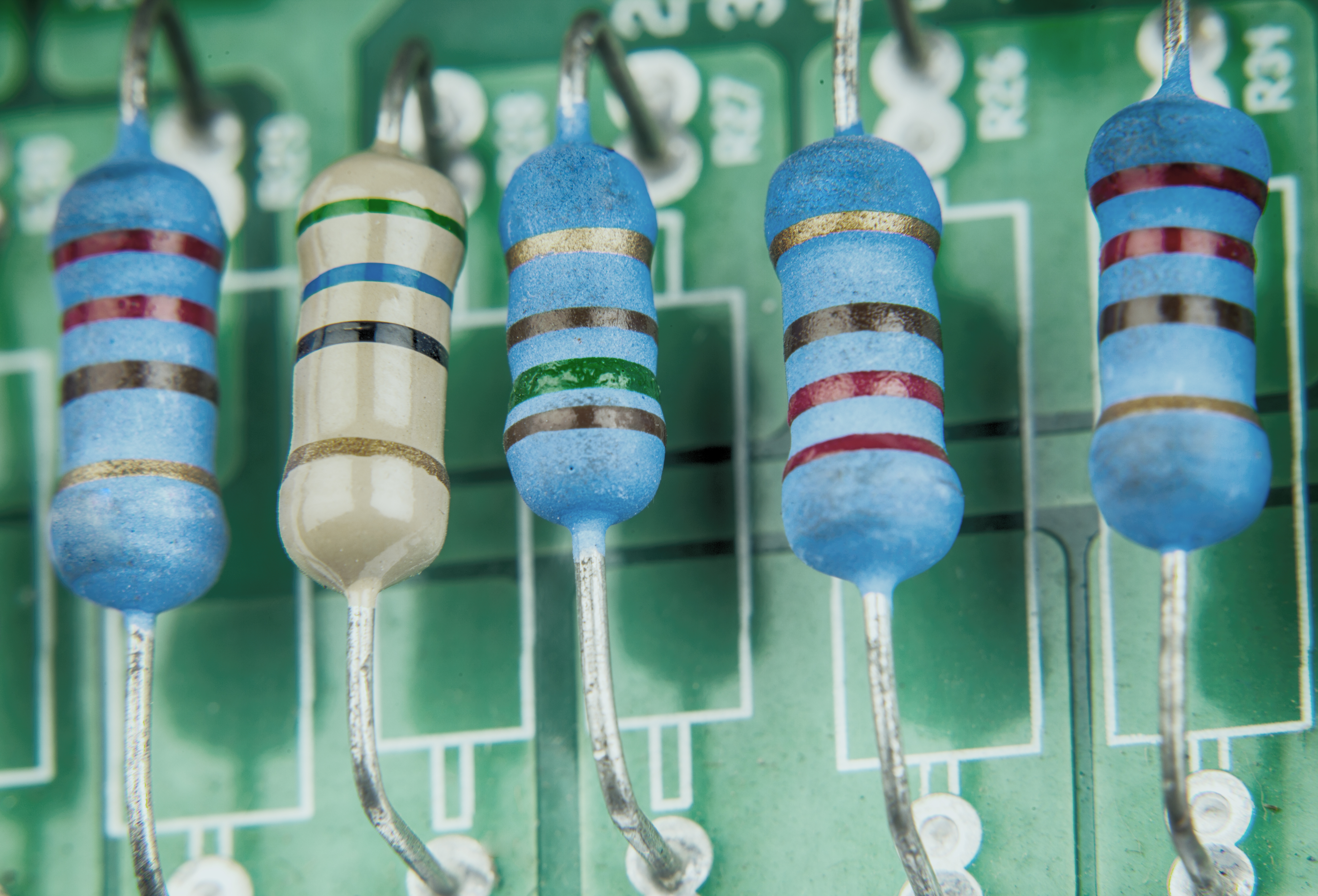
Help To Identify Resistor To Remove Electrical Engineering

What Happens When A Resistor Burns Up Sciencing

What Happens When A Resistor Burns Up Sciencing

How To Test Resistors 9 Steps With Pictures Wikihow

How To Test Resistors 9 Steps With Pictures Wikihow

Resistance Multimeters Adafruit Learning System

Resistance Multimeters Adafruit Learning System

How To Measure Inductance Daycounter

How To Measure Inductance Daycounter

13 Common Pcb Soldering Problems To Avoid Seeed Studio Blog

13 Common Pcb Soldering Problems To Avoid Seeed Studio Blog

Resistors Ohm S Law Electronics Textbook

Resistors Ohm S Law Electronics Textbook

Comments

Popular posts from this blog

Induction Cooker Design With Quasi Resonant Topology Using Jitter Drive Method

Although quasi resonant topology offers a more cost effective implementation it introduces more emi problems. 58 may 2013. Analysis And Design Method For Parallel Quasi Resonant Induction Cooker Design With Quasi Resonant Topology Using Fundamentals Of Power Electronics Of Power Electronics Most induction cookers are based on half bridge topology. Induction cooker design with quasi resonant topology using jitter drive method . Induction cooker design with quasi resonant topology using jitter drive method at articletulu2013inductioncd titleinduction cooker design with quasi resonant topology using jitter drive method authormustafa tulu and deniz yildirim journal2013 12th international conference on environment and electrical engineering year2013 pages1 6. Proceedings of the international conference on environment and electrical engineering eeeic. Designing an...

How To Test Transient Voltage Suppression Diode

Transient Voltage Suppression Diode Devices New Transient Voltage Suppression Diodes From Details About 100x 5kp60a Diode Transient Voltage Suppressor Glass Passivated 5kw 5000 Watts Transient Voltage Suppressor Diodes Tvs Selection Guide Application Hints For Transient Voltage Suppression Diode Transient Voltage Suppressor Diode Tested In Aeronautical How To Read Data Sheets Tvs Diodes Eeweb Community Surge Protection Circuit Principle And Design 5kp15ca 15v 24 4a Bidirectional Transient Voltage Suppression Diode How To Use Tvs Diodes For Transient Voltage Suppresison Tvs Diode Arrays Tvs Diodes Littelfuse Tvs Diode For S...

Diode Circuit Of Logic Gates

Diode Or Gate For Positive And Negative Logic Or Gate And Gate Logic With Diodes And Transistors Digital Electronics Logic Gates Basics Tutorial Circuit Digital Logic Gate Tutorial Basic Logic Gates What Is The Function Of A Diode Logic Gate Quora Diode Logic Circuits Diode And Gate Diode Or Gate Diode Logic Wikipedia Solved 10 The Circuit Shown Here Is A Type Of Logic Gate How To Build A Diode Or Gate Circuit Digital Logic Or Gate C H A P T E R 4 Diodes Non Linear Devices Ppt Video Diode And Gate For Positive And Negative Logic And Gate Basic Logic Gates Using Discrete Components ...